Variothermal Molding for Mass Production

Mass production of microfluidics requires replacing PDMS with thermoplastics. Variothermal molding solves the “frozen layer” problem, enabling cycle times of <1 minute.
Microfluidic diagnostics are moving from university labs to global production lines. However, standard “soft lithography” methods used for prototyping do not scale. Mass production relies on injection molding, but this process faces a critical physical barrier at the microscale. Standard molding fails when filling channels smaller than ten microns. The high surface-area-to-volume ratio causes the molten polymer to solidify instantly upon contact with the cold mold. This creates a “frozen layer” that blocks the flow path, resulting in short shots. Consequently, manufacturers must adopt Variothermal (Rapid Heat Cycle) Molding to overcome this thermal resistance and achieve high-fidelity replication.
You can also read: Bio-Based Media for Micro- and Nanoplastics Removal.
Solving the “Frozen Layer”
The “frozen layer” creates a skin that drastically increases flow resistance. In thin wall micro-molding, the pressure required to push through this solidified skin often exceeds machine capabilities. Variothermal technology solves this by dynamically cycling the mold temperature.
The process heats the mold to near the polymer’s glass transition temperature before injection. For example, in CTC filtration chip protocols, the mold is heated to 130°C during the filling phase. This prevents the melt from freezing upon contact. Experimental data show that a 20 °C increase in temperature reduces viscosity by more than 57% in 0.2 mm cavities. Once filled, the system rapidly cools the mold to 70°C for demolding. This cycle allows the melt to fill the 6 μm micro-ridge corners perfectly before solidification.
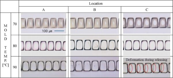
Microscopy evaluation captures the structural replication fidelity of injection-molded tapered micro-ridges. The visual comparison tracks dimensional accuracy across three specific Variothermal mold temperatures (70, 80, and 90 °C) at varying distances from the injection gate. Courtesy of Scalable fabrication of plastic microfluidic chips via injection molding and ultrasonic welding for CTC isolation.
Material Selection: Abandoning PDMS
Lab-scale devices typically use PDMS (silicone), but this material is unsuitable for industrial scale. It suffers from low mechanical stiffness and absorbs small hydrophobic molecules, which skew biochemical assay results. Therefore, mass production shifts to Cyclic Olefin Copolymer (COC) and Cyclic Olefin Polymer (COP).
These thermoplastics offer glass-like transparency and low autofluorescence. This optical clarity is critical for signal-to-noise ratios in fluorescence imaging diagnostics. Furthermore, unlike PDMS, COC exhibits high resistance to polar solvents like acetone and methanol. It also demonstrates low protein adsorption, ensuring that biological samples remain pure. Crucially, COC provides the mechanical stability required for high-volume automated handling.
Venting and Sealing Strategies
Trapped air destroys micro-features. In 5-micron channels, air creates resistance that the melt cannot overcome, causing the “diesel effect” (burn marks). Conventional vent slots are too large and would clog with polymer. Therefore, engineers employ active vacuum venting to evacuate air to pressures lower than 6 mbar before injection. Advanced tools also use porous steel inserts that allow gas escape without permitting polymer flow.
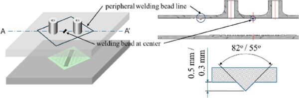
Engineers designed specific welding bead geometries to achieve hermetic ultrasonic bonding of the microfluidic chip. The layout utilizes a continuous peripheral bead to seal the outer edges and a central spot weld bead to structurally reinforce the micro-ridge land contact. Courtesy of Scalable fabrication of plastic microfluidic chips via injection molding and ultrasonic welding for CTC isolation.
Once molded, the chips require sealing without blocking the delicate channels. Ultrasonic welding provides the solution. The process uses a peripheral welding bead, often five hundred μm high with an 82° tip, located on the chip’s outer boundary. Fusion occurs only at this bead. The functional micro-channels are pressed into “near contact” (5 μm gap) but do not melt. Optimization studies show that 400 J of energy seals the device perfectly. Exceeding this limit causes ridge damage and clogging.
The transition from PDMS to thermoplastics defines the future of medical diagnostics. Variothermal molding bridges the gap between precision and speed. By managing the thermal history of the mold, engineers can now produce lab-on-a-chip devices at industrial scales.