At ANTEC: Class A Straight From the Mold with PU Overmolding
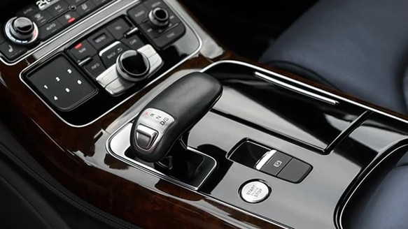
By moving surface formation into the tool, PU overmolding can displace downstream paint operations with a reactive in-mold skin that stabilizes gloss and optical uniformity.
Paint operations remain prevalent because they mask molding defects and deliver a consistent appearance at the production scale. They add unit operations and tighten coupling across the process chain, which increases the likelihood of out-of-window process deviations. Teams route parts through cleaning, priming, coating, curing, inspection, and rework. Each additional handoff increases susceptibility to contamination, handling damage, and yield loss. Curing ovens impose substantial energy demand, while coating operations expand regulatory and compliance burden. Polyurethane (PU) overmolding reverses the sequence by forming the cosmetic surface within the mold, so the part exits the press with a finished Class A surface already in place. At ANTEC 2026, Dan Rozelman from KraussMaffei discussed a Class A PU overmolding and in-mold surface formation.
You can also read: Controlling Gloss and Surface Appearance in Injection Molding.
Why Class A Pushes Manufacturers Past “molded-in color.”
Class A surfaces demand tight control of surface topography and optical uniformity. Raking light exposes waviness, gloss nonuniformity, sink read-through, flow marks, and texture mismatch. The surface must also satisfy durability targets for scratch and mar resistance, UV stability, and chemical resistance. Uncoated thermoplastics may meet appearance requirements on small components, but large A-surfaces amplify marginal defects and process signatures. Those parts still require ribs, attachment features, stiffness, impact resistance, and dimensional stability. This mismatch drives layered architectures that decouple load-bearing function from cosmetic performance.
The Two-Layer Concept: Carrier and Reactive Skin
Polyurethane overmolding starts with a structural carrier. The press injection-molds the carrier from a thermoplastic, or the tool locates a composite substrate. The carrier establishes nominal geometry, stiffness, and attachment architecture. The cell then runs a second operation that doses, mixes, and delivers a low-viscosity reactive polyurethane system into the closed cavity onto the carrier surface. The formulation wets the substrate and advances as a controlled flow front across the Class A field. It then progresses through crosslinking cure kinetics while the tool enforces defined pressure loading and thermal boundary conditions. After gelation and solidification, the part ejects with a continuous PU skin that functions as the final optical surface.
This approach internalizes finishing within the tool, reducing post-mold handling and limiting particulate uptake during cure. It also shifts surface control upstream, since cavity design and cell stability drive appearance and defect formation rather than downstream paint operations.
Tooling and Cell Requirements
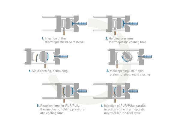
Process schematic for polyurethane in-mold coating/overmolding: thermoplastic carrier injection followed by polyurethane (PU) or polyurea (PUA) injection and in-tool reaction to form the cosmetic skin. Courtesy of KraussMaffei.
The process requires an integrated injection molding and reactive-coating cell. The setup demands high-precision metering and mixing, stable thermal management, and repeatable deposition into the tool. Mold design becomes critical. The cavity must establish a tightly controlled coating gap and preserve thickness uniformity across large aesthetic fields. Sealing must remain robust, since leakage compromises cosmetic integrity and process repeatability. Venting must evacuate displaced air without witness marks, because residual gas entrapment generates bubbles, streaking, and localized gloss loss.
Flow-field design governs surface quality. The coating must deliver uniform areal coverage across large Class A fields and through geometric discontinuities. Sharp corners, thin transitions, and deep draws elevate risk by driving flow-front deceleration, knit-line analogs, and gas entrapment. A robust design optimizes runner and gate architecture, limits local shear-rate gradients, and integrates engineered venting for air evacuation. Many production tools partition carrier molding and coating within an integrated layout to protect surface integrity and maintain cycle efficiency.
Adhesion and Thermal Limits
A flawless surface still fails if the coating loses interfacial integrity. Adhesion depends on chemical compatibility, substrate surface energy, and the carrier’s thermal and processing history. Some substrates support strong bonding, while others require surface activation, primers, or formulation tuning. Thermal expansion mismatch also matters. The PU layer and carrier exhibit different coefficients of thermal expansion, so thermal cycling imposes interfacial stresses. A weak interface can develop edge lift, microcracking, or localized delamination with time.
Interior and exterior parts impose different requirement sets. Interior trim prioritizes scratch resistance, gloss control, and, in some cases, defined haptics, alongside low odor and low fogging performance. Exterior components face UV radiation, moisture, road chemicals, and impact loading. They also face large-area optical scrutiny, where minor surface nonuniformity becomes visible at distance under daylight and directional lighting.
Tradeoffs in Manufacturing
PU overmolding can eliminate downstream finishing steps and reduce the footprint associated with surface-treatment operations. It can also reduce handling-induced damage and improve cosmetic repeatability by forming the surface within a closed, controlled tool environment. The PU skin can provide increased depth-of-image and improved scratch and mar resistance relative to many uncoated thermoplastic substrates. Designers can co-integrate styling surfaces with structural features in a monolithic component, which can reduce assembly count and remove paint-masking constraints.
The tradeoff demands tighter process control. The cell must maintain dosing accuracy, stoichiometric mix ratio, shot timing, and thermal setpoints within narrow limits. The tool must sustain stable sealing and venting performance over extended production runs. Minor drift can trigger immediate cosmetic nonconformance. Repair strategy also changes, since conventional refinish methods may not align with the chemistry and multilayer architecture of an in-mold reactive skin.