MuCell Designer’s Guide: Mastering Microcellular Injection Molding
Foam injection molding is now a mainstream process, and the MuCell® Designer’s Guide equips engineers to master its technical complexity.
Plastics engineers often encounter MuCell®, a microcellular injection molding technology, framed in terms of lightweighting and sustainability. While those drivers are significant, the central engineering challenge is achieving a process that remains stable, predictable, and repeatable under production conditions.
The MuCell® Designer’s Guide addresses this gap by providing a structured reference on SCF–polymer interactions, parameter optimization for cell morphology control, and the integration of simulation tools that allow engineers to translate design intent into reliable molded outcomes.
You can also read: Understanding Supercritical Foaming Technology
Microcellular Physics in Practice
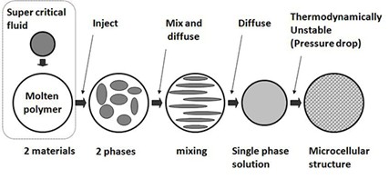
Process Sequence for Microcellular Injection Molding. Courtesy of Green Molding.
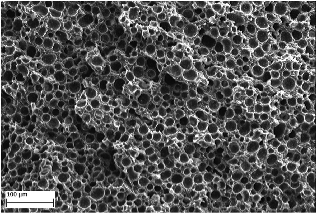
The MuCell process relies on the controlled dissolution of a supercritical fluid (SCF), typically nitrogen or carbon dioxide, into a polymer melt. Under elevated pressure, the SCF disperses homogeneously, producing a single-phase solution. Upon injection into the mold cavity, a rapid pressure drop initiates nucleation. Cells form within the range of approximately 5 to 50 micrometers and expand until the polymer matrix solidifies.
This internal foaming mechanism does more than lower density. It fundamentally changes the rheology of the polymer melt. With dissolved SCF, viscosity drops significantly, improving flow length and reducing injection pressure. The pressure distribution across the cavity becomes more uniform, lowering residual stresses. These combined effects give designers freedom to reimagine part geometries, mold layouts, and machine requirements.
Engineering Benefits with Measurable Parameters
Weight reduction is perhaps the most visible outcome of MuCell, but the Designer’s Guide emphasizes it as a controlled parameter rather than a byproduct. Achievable reductions fall in the range of 5–40%, depending on SCF concentration, polymer grade, and mold geometry. Engineers monitor density reduction ratios closely to ensure the foaming contributes to performance rather than undermining it.
Cycle efficiency represents another measurable improvement. Since MuCell eliminates high-pressure pack-and-hold stages, cooling governs the cycle. Shorter cycles, sometimes up to 40% faster, occur particularly in parts with heavy wall sections. Clamp-force requirements often drop by 25–50%, allowing manufacturers to operate molds that once required a 500-ton press on a 300-ton press. These reductions in equipment demand and energy consumption scale directly with production volume.
Dimensional stability represents a critical outcome in technical evaluations. Internal gas pressure counteracts shrinkage during cooling, thereby reducing warpage and minimizing sink marks. Engineers quantify this performance by comparing molded dimensions with CAD specifications and by assessing flatness, roundness, and profile tolerances. Consistent cell morphology within the core further limits variation across production runs.
Design Rules for Engineers
Conventional design rules reflect the limitations of high-pressure solid molding. MuCell shifts those boundaries. With lower viscosity and balanced cavity pressures, engineers reduce wall thickness without risking incomplete filling. Extended flow lengths enable larger or more complex parts with fewer gates.
This shift enables innovative design opportunities. Engineers mold reliable living hinges in a single shot because uniform cell formation distributes stress effectively. They also incorporate tear seams directly into airbag modules without secondary cutting or scoring. Rib networks and lattice structures, once avoided due to warpage risks, now offer practical solutions.
Real-world applications confirm these design benefits. Automotive airbag covers molded with MuCell incorporate hinges that remain flexible at –35°C. Manufacturers have molded valve covers with exceptional flatness and weldability, while also reducing press size and cycle time. These case studies illustrate how the guide moves beyond abstract design rules to practical, validated strategies.
Process Optimization and Troubleshooting
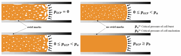
Suppression of Swirl Marks by Gas Counter Pressure in Microcellular Injection Molding. Courtesy of Using P(Pressure)-T(Temperature) Path to Control the Foaming Cell Sizes in Microcellular Injection Molding Process.
A central strength of the Designer’s Guide lies in its emphasis on process control. The SCF dosing rate constitutes the primary parameter governing cell size and density. Insufficient gas yields negligible weight reduction, whereas excessive dosing introduces surface defects.
Thermal management is equally critical. Melt temperature determines the uniformity of SCF dissolution, while mold temperature dictates the final cell morphology. The combined effects of pressure, temperature, and flow rate ultimately define whether the outcome is a fine, uniform foam or an irregular structure characterized by streaks and voids.
The guide provides baseline process windows and structured methods for adjustment. For example, engineers frequently trace silver streaks to premature cell nucleation at the gate, while uneven cell distribution usually points to thermal imbalance across the mold. Rather than depending on trial-and-error, the troubleshooting framework guides engineers through a structured process of root-cause identification, thereby improving efficiency in both time and material usage.
Simulation as a Development Tool
Modern simulation tools have elevated MuCell from a specialized technique to a mainstream option. Software such as Moldex3D and Autodesk Moldflow now incorporate models for SCF dissolution, nucleation, and growth. These programs predict density gradients, shrinkage, and warpage, allowing engineers to evaluate design options virtually.
The Designer’s Guide encourages engineers to set clear weight-reduction or dimensional-stability targets and use simulation to back-calculate process parameters. For example, specifying an 8% weight reduction goal allows the software to optimize SCF concentration, injection speed, and cooling profile. Virtual DOE (design of experiments) runs can explore dozens of parameter combinations before a single physical trial, reducing both cost and lead time.
Applications with Technical Depth
While automotive applications dominate the headlines, the Designer’s Guide frames MuCell as material and geometry-driven rather than industry-specific. Any part where dimensional accuracy, stress reduction, and weight savings intersect is a candidate. Consumer electronics housings can benefit from reduced warpage, medical device casings from lighter yet stiffer structures, and packaging from material efficiency.
By focusing on SCF physics, process windows, and troubleshooting strategies, the guide ensures engineers can adapt the technology to diverse sectors without diluting performance.
From Concept to Practice
The MuCell Designer’s Guide is a technical playbook, built for engineers who need to understand the physics of supercritical fluids, the nuances of processing windows, and the predictive power of simulation. By framing benefits as measurable parameters, offering structured troubleshooting methods, and integrating simulation into workflow, it provides the tools to make microcellular injection molding both practical and scalable.