Designing Plastic Parts: Are You Considering Creep?
The successful design of plastic parts is complicated, primarily as they are made of plastic. Yep … I meant to say that. Plastics create a significant challenge not only to manufacturing but also to part design and performance. We commonly overlook the degree of complexity as the benefits of using plastic overwhelm their negatives. However, many have accepted the shortfalls rather than trying to advance beyond these limitations. This has happened in both design and manufacturing.
Plastics – both fluid & solid
In their fluid, or molten state, plastics do not follow normal Newtonian flow behavior and are referred to as pseudo-plastic non-Newtonian. Non-Newtonian fluids are somewhat abstract and fall outside what is studied in most engineering degree programs. Mechanical engineering focuses on the more traditional Newtonian fluids while studying fluid mechanics or fluid dynamics in college.
The subject of non-Newtonian fluids may be skimmed, but rarely is comprehensively covered. Non-Newtonian refers to the fact that the viscosity of a fluid is directly influenced by shear rate. The viscosity of pseudo-plastic non-Newtonian fluids decrease with increasing shear rate, i.e., the faster you flow in a channel, the lower the viscosity.
In addition, the viscosity of plastics is also influenced by temperature and pressure. In their solid phase, plastics are considered to have viscoelastic properties. This refers to the fact that they not only have the characteristics of an elastic solid, but also of a viscous fluid. Odd! Initial loading is dominated by the elastic
behavior. However, immediately after the viscous characteristics become evident and cause what we call creep. Given a part under constant strain, like a plastic boss holding a metal insert, the boss will experience stress relaxation. This is another viscoelastic characteristic.
Engineering design
For engineering design applications, the most fundamental material property of a solid material is its modulus. This defines its rigidity. With most non-plastic materials used in engineering applications, the material’s modulus is well understood and often can be treated as constant within normal use conditions, i.e., a single value modulus is sufficient. This is particularly the case with metals, and is in stark contrast to what engineers should be doing when working
with plastics.
In contrast to metals, the modulus of plastics can vary dramatically due to a very wide variety of things. These can include nearly all process parameters, in cavity flow conditions, environment and application. Even in what are considered normal use conditions, modulus can change constantly. An example of this contrast is that a change of 100 °C has a negligible influence on the modulus of most structural metals, whereas with plastics the influence on modulus can be significant. Of particular interest in this article is the viscoelastic nature of plastics that requires us to also consider the influence of time, strain and strain-rate on modulus.
Sample Problem:
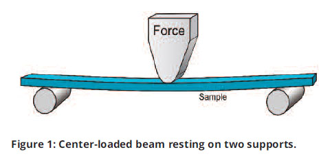
Let’s make a contrast of calculating the deflection of a simple beam with a metal and a plastic material. Consider a bar that is 0.125 in. thick and 0.5 in. wide resting on supports that are 3.5 in. apart (see Figure 1).
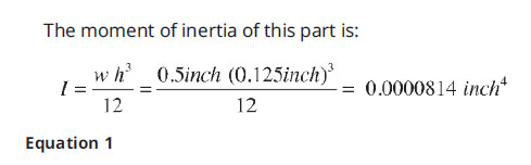
*Note: Moment of inertia defines the flexural rigidity of the shape and will be the same whether the part is made of metal or plastic.
Assume it is important to determine how much this part will deflect given a center load of 600 lbs. The supplier of the steel provides the design engineer a published modulus of 30 million psi for the metal being used. With this information, the engineer can calculate deflection (see Equation 2).
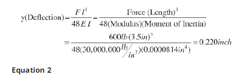
Assuming there are no unusual conditions that this bar will experience in application, the engineer would have a high degree of confidence that these calculations would accurately predict the deflection of this part.
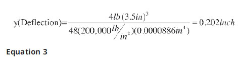
Now consider you are looking to do the same thing with a plastic specimen made from a polypropylene homopolymer (Braskem F006EC2) having a published flexural modulus of 200,000 psi. In this case the load is only 4 lbs. (Note: as the modulus of the metal is 150 times that of the PP, I have selected a load that is 1/150th that used for the metal). In this case, the actual dimensions of the injection molded bar are 0.129 x 0.495 in. The corrected moment of inertia, therefore, is 0.0000886 in4. Deflection is then calculated using the same Equation 2 (see Equation 3).
Again, assuming there are not any unusual conditions that this bar will experience in application, the engineer should have a very low degree of confidence that the calculated deflection will be the same as would be seen in application. The problem here is that what might be considered “normal conditions” for many materials, is not necessarily normal for plastics. In an actual flexural test of this sample, deflection was initially found to be 0.150 in. – not the 0.202 in. that was calculated. This is a 26% error, which should be considered significant.
What was missed by the engineer here is that before doing such an analysis, many questions need to be asked and further data collected.
So what has happened? If we look further at the material supplier’s information, the modulus of the material was taken as a 1% secant modulus under common ASTM conditions including a deflection rate of 0.05 in./second.
In contrast to the ASTM test, the actual deflection of 0.150 in. occurred when the weight was applied to the bar by hand. Even when carefully placing the weight on the bar, the deflection occurred nearly immediately, i.e., the strain rate was significantly faster than the ASTM 0.050 in./minute and was closer to 0.150 in./second. This strain rate is about 180 times faster and should be expected to increase the modulus of viscoelastic materials. (Note: Increasing strain rate will increase the stress and modulus of a viscoelastic polymer).
Looking further at the published material data, the modulus is a secant modulus taken at a 1% strain. At the 0.050 in./minute deflection rate used in the ASTM test it would take about four minutes for the sample to reach the 1% strain.
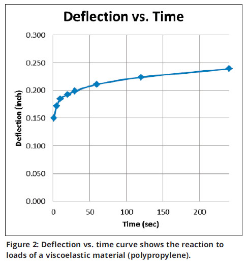
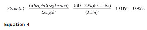 In contrast, the 1% strain was achieved nearly instantly in my test when the part deflected 0.150 in. (see Equation 4) showing a 0.95% stain developed). After initial loading of the 1 lb. sample, the part continued to deflect due to its viscoelastic characteristics. The deflection over the next four minutes is shown in Table 1 and graphed in Figure 2.
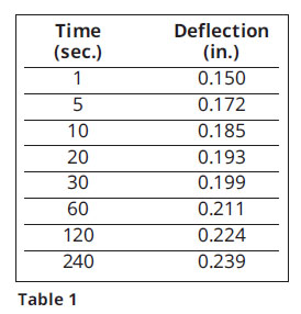 Note that at the four minutes it took the ASTM sample to reach a 1% strain, the parts deflection in this test has increased from 0.150 to 0.239 in. This is an increase of almost 60% and has now exceeded the original calculated deflection of 0.202 in. (Equation 3). What we are seeing is the immediate elastic deflection of the sample (0.150 in.) followed by the viscous deformation of a viscoelastic material. The viscous reaction is what we normally refer to as creep.
So, the natural questions may be – how long will this continue to deflect and is this unique to polypropylene. The answer is – this deflection will continue indefinitely, or at least until the bar flexes enough that it slides off the supports and lands on the floor. And no, this is not unique to polypropylene.
Engineering with viscoelastic materials
 Most people involved with plastic product design and materials have at least a basic understanding of creep. We know that plastic parts will continue to deform over time under a constant load. An example being a heavy coat stored for several years in a closet on a plastic coat hanger. With time, the heavy load of the coat will slowly distort the coat hanger, possibly to a point where the coat ends up on the floor. Though this creep phenomenon is generally understood, it often is ignored during the design phase of many products. This lack of attention can come from the lack of creep data available to a designer, the lack of understanding of how to use the data if it is available, and the lack of appreciation of the impact that creep may have on the failure of a product.
The first problem in dealing with the viscoelastic characteristics of plastics is the lack of material data. This is a time and cost challenge compounded by the above-noted issues.
ASTM D 2990-09 defines how to derive tensile, compressive and flexural creep. The method includes taking deflection measurements for a given load up to 1,000 hours and then using this to graph Strain vs. Time. Data can be represented as Strain vs. Time, Strain vs. Log Time or Log Strain vs. Log Time. Ideally creep data should be taken at least four different loads (stresses). From this, one can derive isochronous stress-strain curves. Additionally, data can be presented as Modulus vs. Time at a given stress. Given data collected over 1,000 hours, it is common that this data can be extrapolated with reasonable accuracy to 100,000 hours (approximately 11 years).
Using creep data
Ideally an engineer wants to know how something is going to behave not only during its initial application, but also years down the road. With a viscoelastic material under continual stress we cannot use single-point modulus data and calculate anything of value. Even looking at short-term behavior characteristics is questionable (as I will present later). What’s needed is creep data.
The following describes a simple experiment demonstrating how creep data can be generated and applied. This creep test is conducted over just 300 hours and is not intended to advocate a shorter test than the normal 1,000-hour test. Its intent is more to help demonstrate the process and how the data can be generated and can be used.
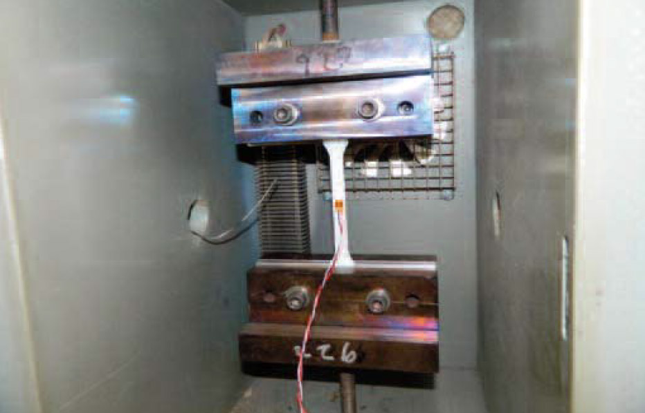
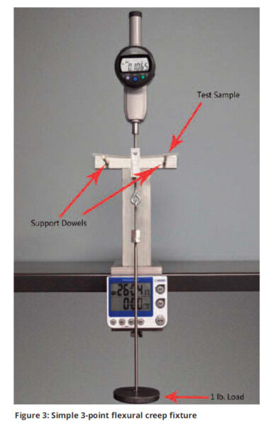
To begin, I will demonstrate with a simple flexural creep fixture shown in Figure 3. A sample is suspended between two metal rods (like that illustrated in Figure 1). A dial indicator is placed on the sample and zeroed. Finally, a load is suspended, timer is started and deflection readings are taken over the next 300 hours. The plastic sample and suspended unsupported length (3.5 in.) are the same as described in the earlier sample problem.
The material is a polypropylene homopolymer (Braskem F006EC2) and the center load is 1 pound. Data was collected over 12+ days (300 hours). The 1-lb. load results in a stress of 637 lbs. (see Equation 5).
The deflection readings from the dial calipers were converted to stain per the formula in Equation 4. Figure 4 shows the resultant creep curve.
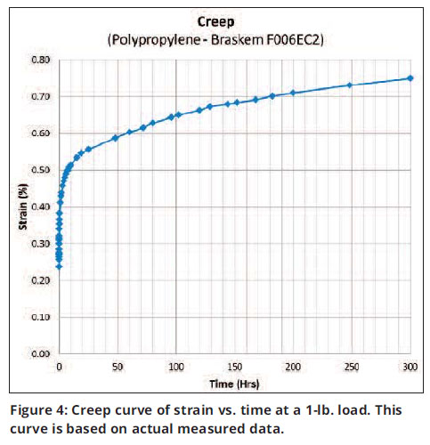
During loading there was an immediate elastic deformation resulting in a strain of 0.24%. This was followed by a continuous viscous deformation over the next 300 hours.
Note that after initial loading, viscous strain increases dramatically over the next 20 hours, from 0.24% to more than 0.55%. From 20 to 300 hours the rate of change decreases significantly, but continues at a fairly steady rate.
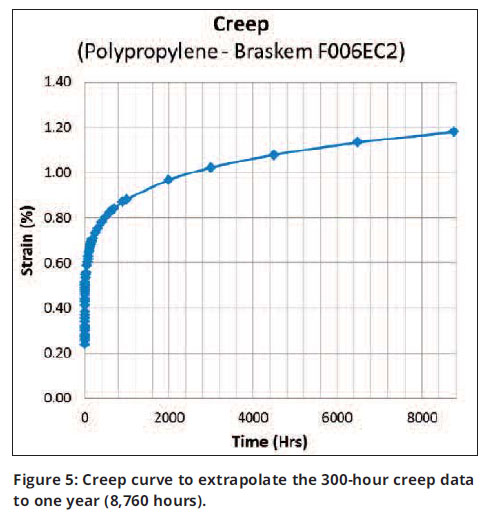
After deflection appears to stabilize (after 50 hours in this graph), this later data can be organized into a log-log graph. Here a power-law model can be fit to what should be relatively linear data. The resultant power law equation can then be used to extrapolate strain at any time within the measured data range and beyond this range. The extent of further extrapolation depends on the stability of the data generated. It is fairly common that data from a 1,000-hour creep test is extrapolated to 100,000 hours.
Figure 5 shows a creep curve where I have used this method to extrapolate the 300-hour creep data to one year (8,760 hours).
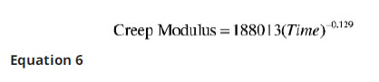
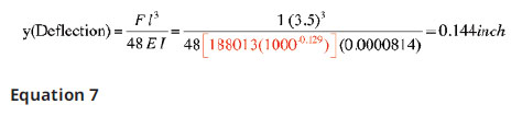
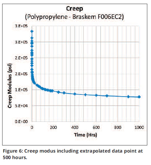
The creep data from this test can also be reformatted to be displayed as Creep Modulus vs. Time. Using the same method described above for extrapolating strain vs. time data, we get the creep modulus formula below (Equation 6). Modulus is then extrapolated to 1,000 hours (see Figure 6).
In this case I will substitute the creep modulus formula directly into Equation 2 to calculate deflection of the bar at 1,000 hours (see Equation 7).
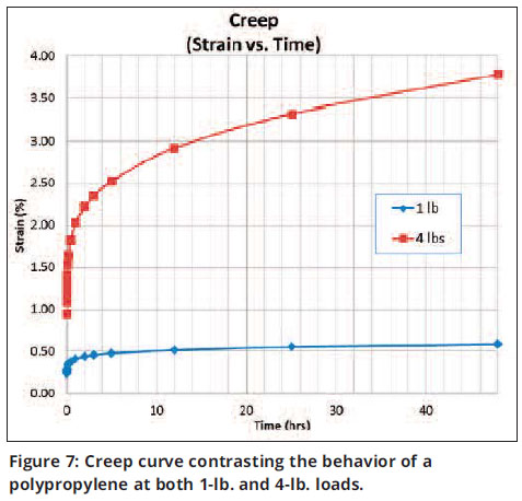
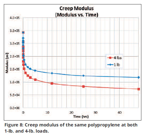
The above creep test was repeated with a 4-lb. load and is contrasted to the data from the 1-lb. load in Figure 7. Here the 4-lb. load resulted in a 0.150-in. deflection (0.95%) vs. a 0.0375-in. deflection (0.24% strain) with the 1-lb. load.
Figure 8 presents this same data as Creep Modulus vs. Time. What is interesting to note is the modulus of the two materials is nearly identical at the initial loading. As discussed earlier, this is at a significantly higher strain rate than standard ASTM testing of 0.050 in./minute. However, this placing of a load on a structure is much more realistic than the controlled slow rate conducted during the ASTM testing.
In summary
I’ll start by saying it again – plastics are complicated. And far too often we oversimplify working with them … to the detriment of the industry. If an engineer is trying to do any structural design requiring a material’s modulus, single-point data is virtually garbage. Kind of like having a car that has one speed – 60 mph. Great for one thing – the highway, but a little crazy getting to the highway and back to your house.
 The modulus of plastic materials changes in reaction to many things. In addition to the more obvious influence of temperature, the viscoelastic characteristics will cause a behavioral change resulting from stress (how much of a load or force is acting on it), strain (how much a part is deformed), strain rate (how fast it is deformed), and time (how long a part is under a stress or strain). The result is that designing and making plastic parts is like building a house on a foundation of Jell-O … things will move. But we still do it all the time. Can we do better? Yes.
 This article took a simple approach to looking at creep using a jig that could be cobbled together by nearly anyone. Note that in this study the immediate loading of both the 1-lb. and 4-lb. sample resulted in a modulus that was nearly 150% of the published modulus for this material. This shows the significant impact of strain rate on material properties.
I find it interesting that the immediate modulus determined from use of both the 1-lb. and 4-lb. loads were nearly identical. However, the creep modulus under the two loads began to quickly diverge immediately after initial loading (see Figure 8). It also should be noted that after only 10 hours, the 4-lb. load resulted in a creep modulus that was half that of the published modulus. This tells us that within 10 hours, deflection of any part made from this material would double relative to any engineering calculations using the published single-point modulus.
Remember, viscoelasticity is a characteristic of nearly all the plastic materials we work with. This includes what we consider to be engineering resins. The magnitude of creep will vary, and in most cases, be less than what I showed here. Additives such as glass, carbon, talc, mica, etc., should reduce creep.
If you are engineering a part where you should be concerned with creep and you cannot find data, you can contract with numerous material testing labs across the country to do it for you. Cost for conventional creep data at a single stress should be approximately $3,000. When working with a quality lab they may also ask you about other conditions the intended part may experience, such as temperature, as well as whether the test should be done in tension, flexural or compression.
Currently the biggest issue is that you need to plan ahead, as the standard ASTM test needs 1,000 hours. From this you commonly can extrapolate to more than 11 years. However, research being done of time-temperature superposition using DMA creep data shows promise of predicting behavior over centuries after only a day of testing. This is significant and could well revolutionize plastic product design.
This article was written by John Beaumont, American Injection Molding Institute and originally appeared in Plastics Engineering magazine in 2017.
Plastics Engineering keeps plastics professionals worldwide up to date on the latest trends and innovations in materials, equipment and process technologies that impact all aspects of product development and applications in the plastics industry.